Create you own simple circuit that activates with a switch you build from conductive material. You can use the power and ground pins on your Arduino to power your circuit.
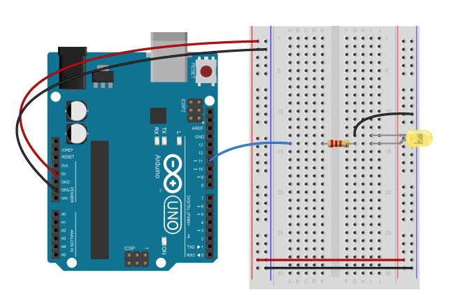
Run the default "blink" sketch with the build-in LED on your Arduino. You can find the sketch by going to File > Examples > 01. Basics > Blink.
Write a blog post about your experience. Document your circuit with photo and/or video. How does it work? How did you make it? What questions are you left with?
If possible, bring you circuit to class.
ITP Lab: Setting up a breadboard
ITP Lab: Using a multimeter (if you use an Arduino to power the board, ignore the Voltage regulator)
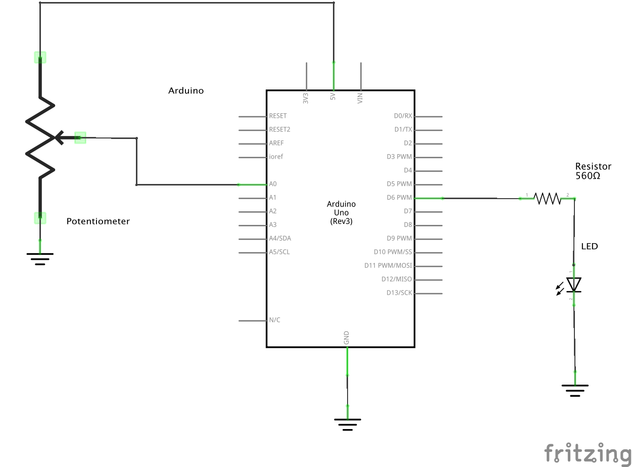
Create another circuit or modify your existing circuit, this time using the Arduino to read your input and to affect your output.
Write a blog post about your experience. Document your circuit with photo and/or video. How does it work? How did you make it? Include successes/failures/questions.
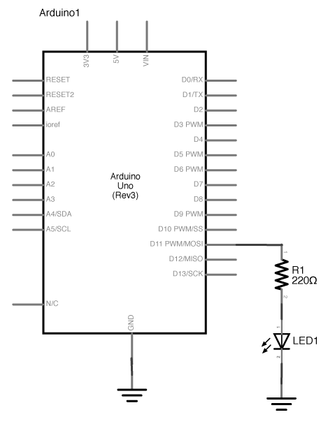
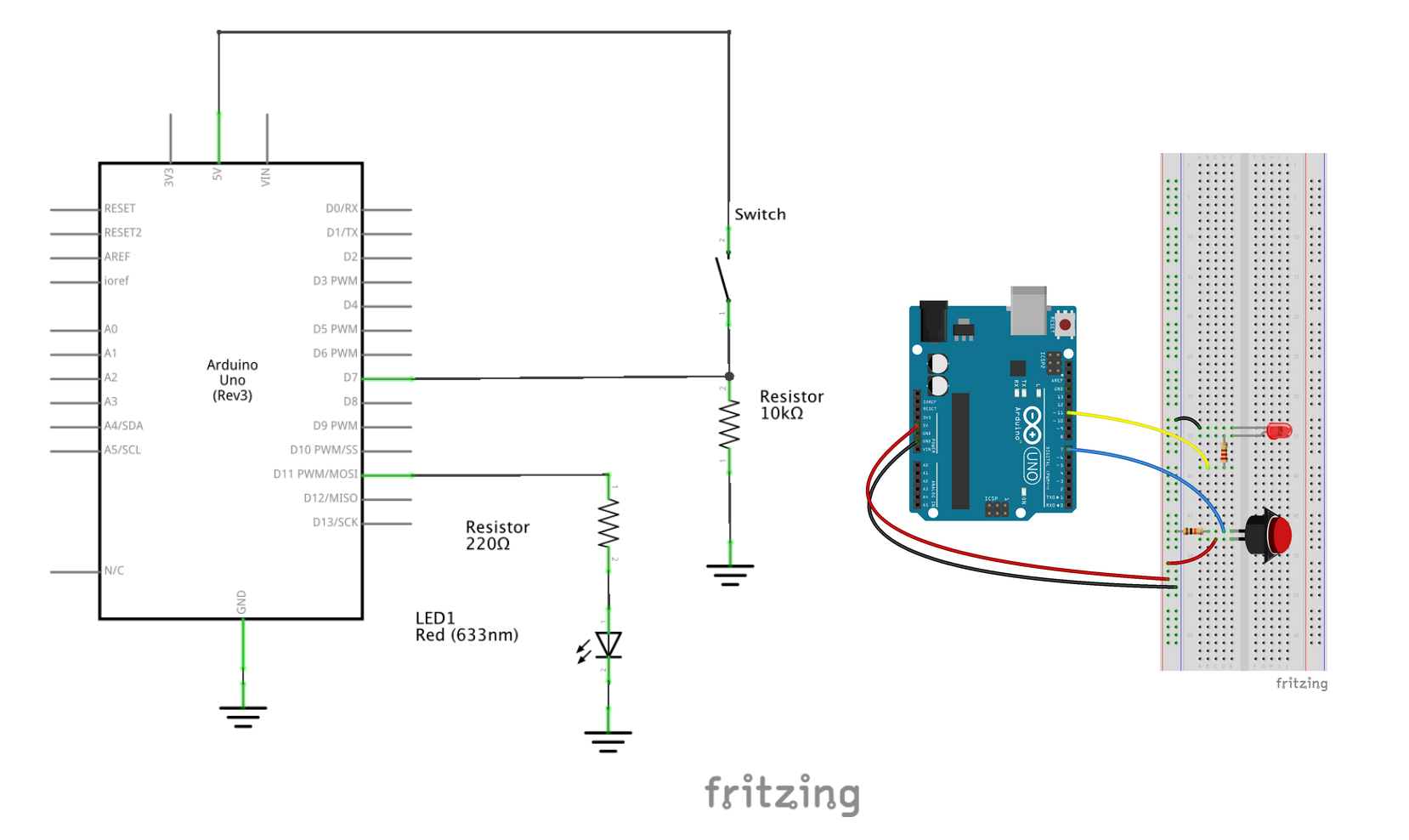
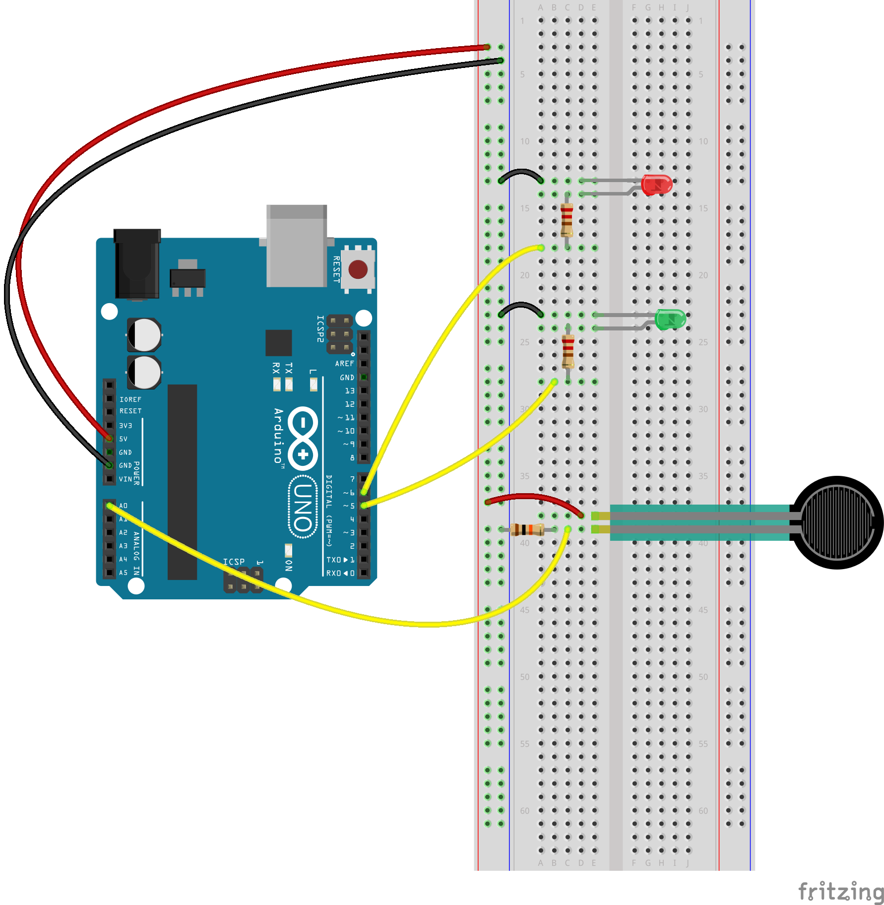
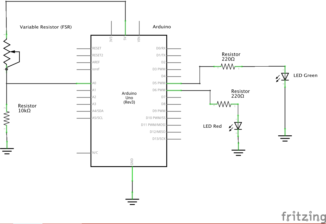
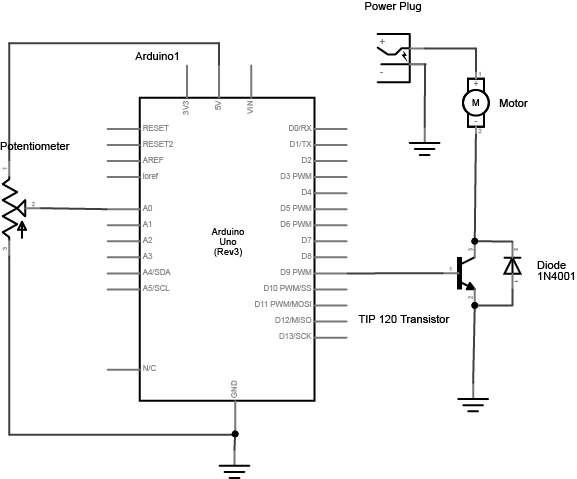
Here is our schematic from class. Note if you do not have a 220 ohm resistor, anything between 220 and 1k should still work (1k might not be very bright though...).
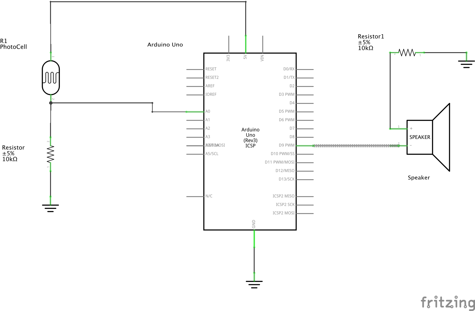
Create circuit that makes use of Analog inputs and outputs where the interaction centers anywhere except the hands. If you choose to use hands then try getting your hands on an analog sensor that is NOT a potentiometer.
Blog Post 1: Document your work. Include schematics.
Blog Post 2: Research a sensor, and blog your findings. What does the sensor sense? How does it work? What are some applications of the sensor? Is there anything noteworthy about its construction or history? Include any relevant photos or videos.
Use the P5 web editor to draw shapes and use variables to somehow animate them. This could be a portrait, a scene, an initial video game prototype, etc.
For your blog, explain what you made and include a link to your sketch.
Build on last week or create a new P5 sketch that uses the mouse or keyboard to make something happen.
For your blog, explain what you made and include a link to your sketch.
Download the latest Serial Control App
Have a look at the Serial Setup Example. Duplicate it and modify, or copy the appropriate lines of code into your sketch.
You can use the schematics and arduino code that print analog or digital values to the serial monitor, which we covered in previous labs.
Get your arduino and p5 sketch communicating. Use a sensor (or sensors) to create a physical interface that changes something in a P5 sketch.
For your blog, describe your idea, process, questions, etc.
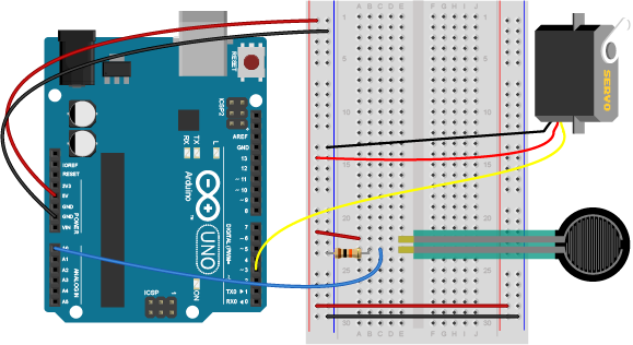
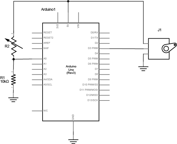
Make something move. Try to use an analog sensor.
Blog about your work. Include code, photo, video, and/or schematics as appropriate.
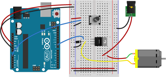
Make something move, light up, or change in the physical world using output from a P5.js sketch.
Blog about your work. Include code, photo, video, and/or schematics as appropriate.
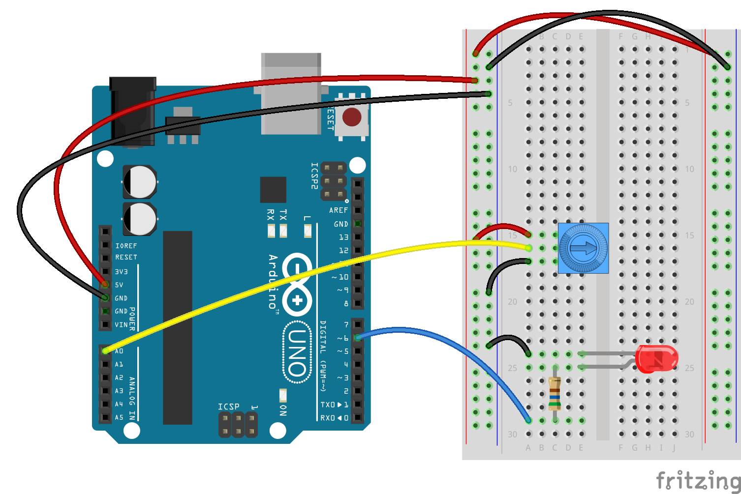
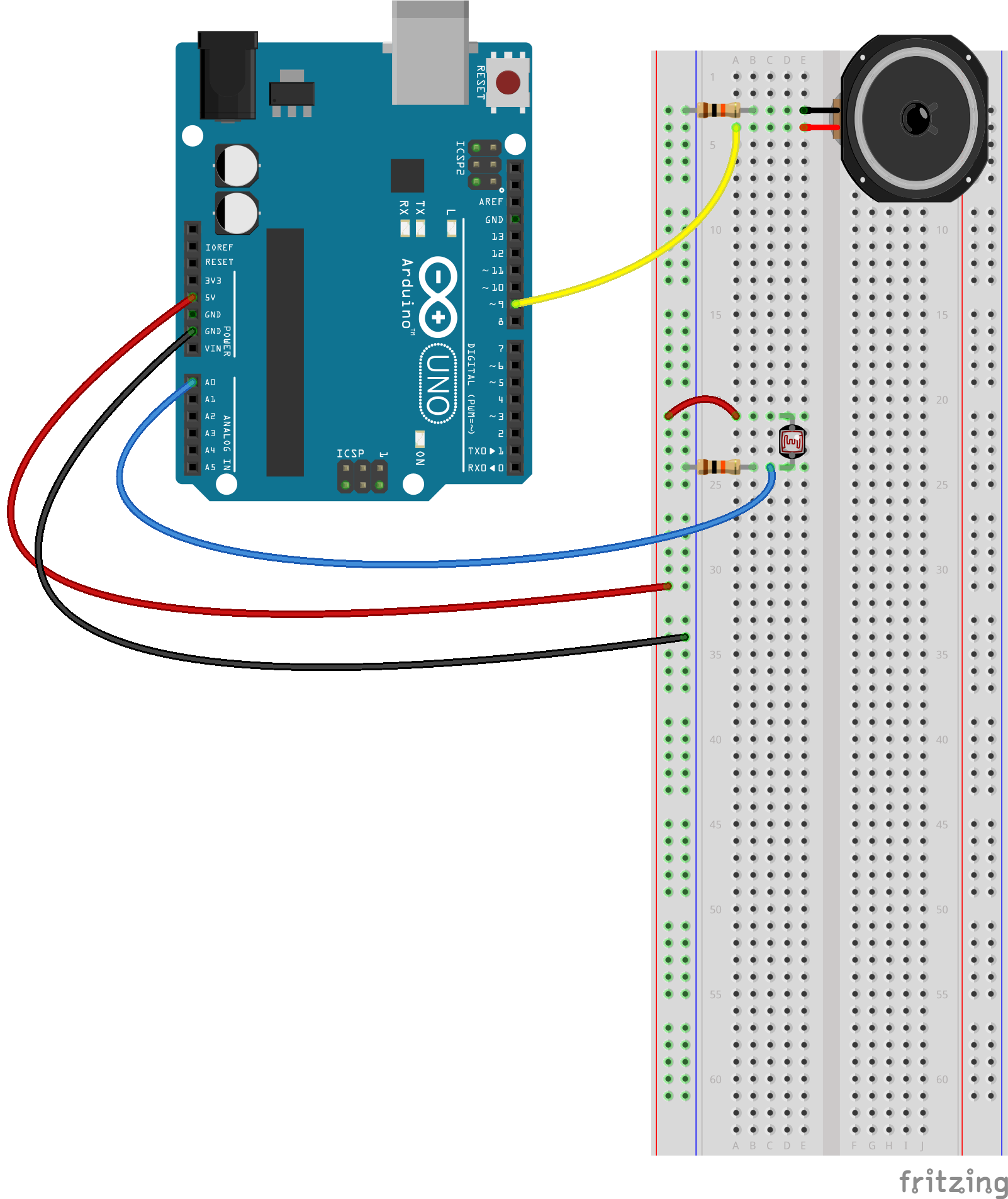
Note that in the schematic below, the LED is connected to a PWM pin. If you used a motor, you can modify the schematic from last week.